Understanding Z-Wave Networks, Nodes & Devices
Z-Wave home automation technology comprises of three layers. The radio layer, network layer and application layer work together to create a robust and reliable network that enables numerous nodes and devices to communicate with each other simultaneously.

- Radio Layer: Defines the way a signal is exchanged between network and the physical radio hardware. This includes frequency, encoding, hardware access, etc.
- Network Layer: Defines how control data is exchanged between two devices or nodes. This includes addressing, network organisation, routing, etc.
- Application Layer: Defines which messages need to be handled by specific applications in order to accomplish particular tasks such as switching a light or changing the temperature of a heating device.
The Network Layer
The Z-Wave network layer controls how data is exchanged between different devices (nodes) on the network, it consists of three sub-layers.
- Media Access Layer (MAC): Controls the basic usage of the wireless hardware - these functions are invisible to the end user.
- Transport Layer: Controls message transfer, ensuring error-free communication between two wireless nodes. The end user cannot influence this layer’s functions but the results of this layer are visible.
- Routing Layer: Manages Z-Wave’s “Mesh” capabilities to maximise network range and ensure messages get to their destination node. This layer will use additional nodes to re-send the message if the destination is outside of the “direct” range of the transmitting node.
The Media Access (MAC) and Transport Layers Explained
Rather like sending a text message, you can’t see how the information transfers from your phone to theirs. You assume that it’s sent and will be received and read by the recipient. Similarly, wireless home automation technologies use the same principles to enable communication between sender and receiver nodes.
Occasionally, a message may get lost.
In a mobile phone’s case, it could be due to poor reception. In the case of a home automation network it could be due to interference or positioning the receiver too far away from the sender. In a simple network, the sender gets no feedback on whether the message has been received and if the command has been executed correctly. This can cause stability problems, unless the installation was planned and tested correctly.
Z-Wave is the one of the most reliable wireless technologies, every command sent is acknowledged by the receiver which sends a return receipt to the sender. This doesn’t guarantee that the message was delivered correctly, however, the sender will get an indication that a situation has changed, or an error has occurred.

Figure 2 - communication with and without acknowledgment
The return receipt is called Acknowledge (ACK). A Z-Wave transceiver will try up to three-times to send a message while waiting for an ACK. After three unsuccessful attempts the Z-Wave transceiver will give up and report a failure message to the user. The number of unsuccessful attempts is also a good indicator of the network’s wireless connection quality.
Using Nodes for Successful Communication
A network consists of at least two nodes. To be able to communicate with each other, the nodes need to have access to a common media or need to have “something in common”.
In most cases this is a physical communication media like a cable. The communication media for radio (wireless) is the air, which is also used by all sorts of different technologies - TV, Wi-Fi, mobile phones etc. Therefore, each type of “network” needs to have a defined protocol that allows the different nodes of one network to identify each other and to exclude messages from other radio sources.
Each node in the network also needs to have a unique identification to distinguish it from other nodes in the same network.
The Z-Wave protocol defines two identifications for the organisation of the network.
- The Home ID is the common identification of all nodes belonging to one logical Z-Wave network. It has a length of 4 bytes = 32 bits.
- The Node ID is the address of a single node in the network. The Node ID has a length of 1 byte = 8 bits.
Nodes with different Home IDs cannot communicate with each other, but they may have a similar Node ID. This is because the two networks are isolated from each other.
On a single network (one Home ID) two nodes cannot have identical Node IDs. This means each node can be individually addressed giving you complete control of your own home automation system.
Devices
Z-Wave has two basic types of device:
- Controllers - devices that control other Z-Wave devices
- Slaves - devices that are controlled by other Z-Wave devices.
Controllers are factory programmed with a Home ID, this cannot be changed by the user. Slaves do not have a pre-programmed Home ID as they take the Home ID assigned to them by the network.
The primary controller includes other nodes into the network by assigning them its own Home ID. If a node accepts the Home ID of the primary controller this node becomes part of the network. The primary controller also assigns an individual Node ID to each new device that is added to the network. This process is known as Inclusion.
|
|
Definition |
In the Controller |
In the Slave |
|
Home ID |
The Home ID is the common identification of a Z-Wave network |
The Home ID is already set as factory default |
No Home ID at factory default |
|
Node ID |
The Node ID is the individual identification (address) of a node within a common network |
Controller has its won Node ID predefined (typically 0x01) |
Assigned by the primary controller |
Table 1 - Home ID and Node ID comparison
Example
This network (figure 3) has two Controllers with a factory default Home ID and two other Slave devices which do not have any assigned Home ID.
Before Inclusion
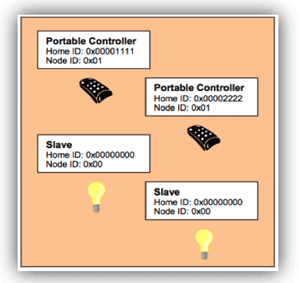
Figure 3 - Z-Wave devices before Inclusion in to a network
Depending on which of the controllers is used to configure the Z-Wave network, the network Home ID in this example will be either #0x00001111 or #0x00002222.
Both controllers have the same Node ID #0x01 and at this stage the slave devices do not have any Node ID assigned. In theory this picture shows two networks with one node in each of them.
Because none of the nodes has a common Home ID, no communication can take place.
One of the two controllers is now selected as being the primary controller of the network. This controller assigns its Home ID to all the other devices (Includes them) and also assigns them individual Node ID numbers.
After Inclusion

Figure 4 - Network after Inclusion
After successful Inclusion, all nodes have the same Home ID - they are connected to the same network. They also each have a unique Node ID, allowing them to be individually identified and communicate with each other.
In this example there are two controllers. The controller whose Home ID, became the Home ID for all devices, is called the ‘primary controller.’ All other controllers become ‘secondary controllers.’
The primary controller can include further devices, whereas the secondary controller cannot. However, the primary and secondary controllers operate the same in all other respects.

Figure 5 - Two Z-Wave networks with different Home IDs co-exist
Because the nodes of different networks cannot communicate with each other due to the different Home ID, they can coexist and do not even “see” each other.
The 32-bit Home ID allows up to 4 billion (2^32) different Z-Wave to networks to be defined, each having a maximum of 256 (2^8) different nodes. However, some of these nodes are allocated by the network for internal communication and special functions, therefore, the Z-Wave network can have a maximum of 232 devices.
Nodes can be removed from a Z-Wave network, this is called Exclusion. During the Exclusion process the Home ID and the Node ID are deleted from the device. The device is reset to the factory default state (controllers have their own Home ID and slaves have no Home ID).
Meshing and Routing
In a typical wireless network the central controller has a direct wireless connection to all of the other network nodes. This requires a direct radio link. However, if there is a disturbance the controller does not have any backup route to reach the nodes and communication will break.

Figure 6 - Network without routing
The radio network in figure 6 is a non-routed network. Nodes two, three and four are within the radio range of the controller. Node 5 is outside the radio range and cannot be reached by the controller.
However, Z-Wave offers a very powerful mechanism to overcome this limitation. Z-Wave nodes can forward and repeat messages to other nodes that are not in direct range of the controller. This enables Z-Wave to create very flexible and robust networks. Communication can be made to all nodes within the network even if they are outside of direct range or if the direct connection is interrupted.

Figure 7 - Z-Wave network with routing
The Z-Wave network with routing (figure 7) shows the controller can communicate directly with the Nodes 2, 3 and 4. Node 6 lies outside its radio range, however, it is within the radio range of node 2. Therefore the controller can communicate to node 6 via node 2. This is called a “route”.
Using this routing system, Z-Wave signals can even work around corners! Other technologies work on ‘line of sight’ where every transmitter must have direct sight of the receiver, but Z-Wave simply sends the signal on a small detour around an obstacle using another node.
Z-Wave’s routing can automatically adapt to any changes in the network. For instance figure 8 shows that direct communication between Node 1 and Node 2 is blocked. But it is still possible for Node 1 to communicate with Node 6 by using Node 3 as an additional repeater.
The more nodes in a network, the more flexible and robust the network becomes.
Z-Wave is able to route messages via up to four repeating nodes. This is a compromise between the network size and stability, and the maximum time a message is allowed to travel in the network.

Figure 8 - Maximum distance between two nodes via four repeaters
Building Routes in a Z-Wave Network
Every node is able to determine which nodes are in its direct wireless range. These nodes are called neighbours. During Inclusion and later on Request, the node is able to inform the controller about its list of neighbours. Using this information, the controller is able to build a table that has all information about possible communication routes in a network. This routing table can be accessed by the user and there are several software solutions, typically called installer tools, that visualise the routing table helping you to optimise the network setup.

Figure 9 - Routing in a Z-Wave Network
The above diagram (figure 9) shows a Z-Wave meshed network, with one controller and five nodes. The controller can communicate directly with node 2 and 3. There is no direct connection to node 4, 5 and 6. Communication to node 4 works either via node 2 or via node 3.

Table 2 - Routing table for the Z-Wave Network
The routing for this network is shown in table 2 - the rows contain the source nodes and the columns contain the destination nodes. A cell with “1” indicates that the nodes are neighbours and a “0” shows there is no direct communication path. The table also shows the connection between Source Node 1 and destination Node 4. The cell between Node 1 and 4 is marked “0“. Therefore the network routes the signal via Node 3 which is in direct range of both Node 1 and Node 4.

Figure 10 - Alternative Z-Wave Netwo Rrouting
Another example (figure 10) shows that Node 6 can only communicate with the rest of the network using Node 5 as a repeater. Since the controller does not have a direct connection to Node 5, the controller needs to use one of the following routes: “1 -> 3 -> 4 -> 5 -> 6” or “1 -> 2 -> 5 ->6”.
A controller will always try first to transmit its message directly to the destination. If this is not possible it will use its routing table to find the next best way to the destination. The controller can select up to three alternative routes and will try to send the message via these routes. Only if all three routes fail (the controller does not receive an acknowledgement from the destination) the controller will report a failure.
Types of Network Nodes
Slaves are categorised as “standard” or “routing” slaves. A routing slave includes advanced routing capabilities.
The difference between the three different node types is their knowledge of the network routing table and their ability to send messages to the network.
|
|
Neighbours |
Route |
Possible functions |
|
Controller |
Knows all neighbours |
Has access to complete routing table |
Can communicate with every device in the network, if route exists |
|
Slave |
Knows all neighbours |
Has no information about routing table |
Can only reply to the node which it has received the message from. Hence, can not send unsolicited messages |
|
Routing Slave |
Knows all neighbours |
Has partial knowledge of routing table |
Can reply to the node which he has received the message from and can send unsolicited messages to a number of predefined nodes he has a route too |
Properties of the Z-Wave Device models
|
Slave |
Fixed installed mains powered devices like wall switches, wall dimmers or Venetian blind controllers |
|
Routing Slave |
Battery-operated devices and mobile applicable devices as for example sensors with battery operation, wall plugs for Schuko and plug types, thermostats and heaters with battery operation and all other slave applications |
Typical Applications for Slaves
Challenges in Typical Network Configurations
Z-Wave network typically starts as a small network that is extended as and when you need. A small network may consist of a remote control and a couple of switches or dimmers. The remote control acts as primary controller and includes and controls the switches and dimmers.
During inclusion the dimmers and switches should be installed at their final location, to ensure that a correct list of neighbours will be recognised and reported.
This type of network configuration works well as long as the remote control can reach all switches and dimmers directly (the node to be controlled is “in range”). If the controlled node is not in range, the user may experience delays, because the remote control needs to detect the network structure first before controlling the device.
In case a device was included and moved afterwards to a new position, this particular device can only be controlled by the remote control if it is in direct range. Otherwise the communication will fail, because the routing table entry for this particular device is wrong and the remote control is not able to do a network scan at the moment of operation.
Z-Wave Network with One Static Controller
Another typical network consists of a static controller - mostly PC software plus Z-Wave USB dongle or an IP gateway together with a number of switches and dimmers.

Z-Wave Network with single static controller
The static controller is the primary controller and includes all other devices.
Because a static controller is bound to a certain location, the other Z-Wave devices must be included while being in direct range with the static controller. They will typically be installed at their final location after inclusion.
Networks with Multiple Controllers
In a larger network several controllers will work together. A static controller is used for the configuration and management of the system and one or several remote controls carry out certain functions in different places.

Z-Wave Network with muliple controllers
If a network has multiple controllers, the user needs to determine which of the controllers will be the primary controller.
Inclusion of a static controller is a challenge, if the devices need to be moved to their final location afterwards. A network re-organisation needs to be performed.
Static controllers are usually more reliable and aren’t easily lost. They typically offer backup functions to replace the hardware in case of severe damage.
Network with Portable controller as the Primary Controller
Remote controls are more vulnerable to damage and loss. Usually remote controls do not offer a backup function. If the primary controller was damaged or lost, a complete re-inclusion of the whole network would need to be performed. However, devices can be included after they were installed, which results in a much more stable network, and no need for network re-organisation.
The choice of the primary controller - static or portable - depends more on your personal preference rather than a technical necessity.
Vesternet is Europe’s leading home automation specialist, take a look at our huge range of Z-Wave products.


